Runner Geometry of Conventional Mold
Runner systems convey the molten material from the sprue to the gate. The section of the runner should have maximal cross-sectional area and minimal perimeter. Runners should have a high volume-to-surface area ratio. Such a section will minimize heat loss, premature solidification of the molten resin in the runner system, and pressure drop.
The ideal cross-sectional profile for a runner is circular. This is known as a full-round runner, as shown. While the full-round runner is the most efficient type, it also is more expensive to provide, because the runner must be cut into both halves of the mold.
A less expensive yet adequately efficient section is the trapezoid. The trapezoidal runner should be designed with a taper of 2 to 5° per side, with the depth of the trapezoid equal to its base width, as shown. This configuration ensures a good volume-to-surface area ratio.
Half-round runners are not recommended because of their low volume-to-surface area ratio. The Three Conventional Runner Profile illustration shows the problem. If the inscribed circles are imagined to be the flow channels of the polymer through the runners, the poor perimeter-to-area ratio of the half-round runner design is apparent in comparison to the trapezoidal design.
Runner Diameter Size
Ideally, the size of the runner diameter will take many factors into account — part volume, part flow length, runner length, machine capacity gate size, and cycle time. Generally, runners should have diameters equal to the maximum part thickness, but within the 4 mm to 10 mm diameter range to avoid early freeze-off or excessive cycle time. The runner should be large enough to minimize pressure loss, yet small enough to maintain satisfactory cycle time. Smaller runner diameters have been successfully used as a result of computer flow analysis where the smaller runner diameter increases material shear heat, thereby assisting in maintaining melt temperature and enhancing the polymer flow. Large runners are not economical because of the amount of energy that goes into forming, and then regrinding the material that solidifies within them.
Runner Layout
Similar multicavity part molds should use a balanced "H" runner system, as shown in the Runner System Layouts illustration.
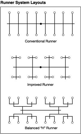
Balancing the runner system ensures that all mold cavities fill at the same rate and pressure. Of course, not all molds are multicavity, nor do they all have similar part geometry. As a service to customers, Dow Plastics offers computer-aided mold filling analysis to ensure better-balanced filling of whatever mold your part design requires. Utilizing mold filling simulation programs enables you to design molds with:
-
Minimum size runners that deliver melt at the proper temperature, reduce regrind, reduce barrel temperature and pressure, and save energy while minimizing the possibility of material degradation.
-
Artificially balanced runner systems that fill family tool cavities at the same time and pressure, eliminating overpacking of more easily filled cavities.
Cold Slug Wells
At all runner intersections, the primary runner should overrun the secondary runner by a minimum distance equal to one diameter, as shown in the Recommended Design of a Cold Slug Well illustration. This produces a feature known as a melt trap or cold slug well.
Cold slug wells improve the flow of the polymer
by atching the colder, higher-viscosity polymer moving at the forefront of the molten mass and allowing the following, hot, lower-viscosity polymer to flow more readily into the mold-cavity. The cold slug well thus prevents a mass of cold material from entering the cavity and adversely affecting the final properties of the finished part.
Runnerless Molds
Runnerless molds differ from the conventional cold runner mold (see Conventional Cold Runner Mold illustration) by extending the molding machine's melt chamber and acting as an extension of the machine nozzle. A runnerless system maintains all, or a portion, of the polymer melt at approximately the same temperature and viscosity as the polymer in the plasticating barrel. There are two general types of runnerless molds: the insulated system, and the hot (heated) runner system.
Insulated Runners
The insulated runner system (see Insulated Runner Mold illustration) allows the molten polymer to flow into the runner, and then cool to form an insulating layer of solid plastic along the walls of the runner. The insulating layer reduces the diameter of the runner and helps maintain the temperature of the molten portion of the melt as it awaits the next shot.
The insulated runner system should be designed so that, while the runner volume does not exceed the cavity volume, all of the molten polymer in the runners is injected into the mold during each shot. This full consumption is necessary to prevent excess build-up of the insulating skin and to minimize any drop in melt temperature.
The many advantages of insulated runner systems, compared with conventional runner systems, include:
- Less sensitivity to the requirements for balanced runners.
- Reduction in material shear.
- More consistent volume of polymer per part.
- Faster molding cycles.
- Elimination of runner scrap — less regrind.
- Improved part finish.
- Decreased tool wear.
However, the insulated runner system also has disadvantages. The increased level of technology required to manufacture and operate the mold results in:
- Generally more complicated mold design.
- Generally higher mold costs.
- More difficult start-up procedures until running correctly.
- Possible thermal degradation of the polymer melt.
- More difficult color changes.
- Higher maintenance costs.
Hot Runners
The more commonly used runnerless mold design is the hot runner system, shown in the Hot Runner Mold illustration. This system allows greater control over melt temperatures and other processing conditions, as well as a greater freedom in mold design — especially for large, multicavity molds.
Hot runner molds retain the advantages of the insulated runner over the conventional cold runner, and eliminate some of the disadvantages. For example, start-up procedures are not as difficult. The major disadvantages of a hot runner mold, compared with a cold runner mold, are:
- More complex mold design, manufacture, and operation.
- Substantially higher costs.
These disadvantages stem from the need to install a heated manifold, balance the heat provided by the manifold, and minimize polymer hang-ups.
The heated manifold acts as an extension of the machine nozzle by maintaining a totally molten polymer from the nozzle to the mold gate. To accomplish this, the manifold is equipped with heating elements and controls for keeping the melt at the desired temperature. Installing and controlling the heating elements is difficult. It is also difficult to insulate the rest of the mold from the heat of the manifold so the required cyclic cooling of the cavity is not affected.
Another concern is the thermal expansion of the mold components. This is a significant detail of mold design, requiring attention to ensure the maintenance of proper alignment between the manifold and the cavity gates. (For more information on thermal expansion, see the information on thermal stress analysis in Thermal Properties.)
Currently there are many suppliers and many available types of runnerless mold systems. In most cases, selection of such a system is based primarily on cost and design limitations — be careful in evaluating and selecting a system for a particular application.